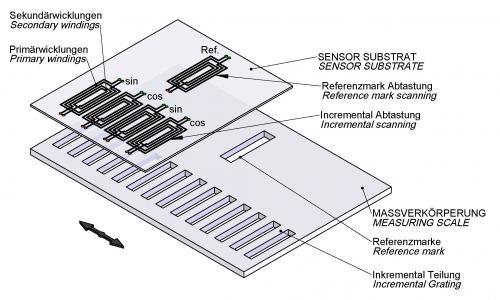
The AMOSIN® encoders operate on the principle of a transformer with a moving reluctance. The mutual inductance of the primary and secondary windings of a transformer changes depending on the relative position with respect to the core. The AMOSIN® system (Fig. 1) consists of a planar micro-coil structure and a measurement scale. The coil structure with a plurality of coils aligned in the direction of measurement (individual sets of micro-coils for Sine and Cosine), is incorporated on a substrate with micro-multi-layer flex circuit technology. The scale is a stainless steel scale with a high-precision photolithographic etched periodic graduation (eg λ = 1000 microns) with variable reluctance.
The relative motion in the direction of measurement between the inductive sensor (encoder head) and measuring scale periodically changes the mutual inductance of each coil and generates two sinusoidal 90 ° phase-shifted signals (SIN and COS). With the excitation pure Sine wave signal, the resultant output is an excellent signal quality and stability against environmental influences so that after the signal conditioning in the evaluation electronics, the error is only 0.1% deviation from the ideal sinusoidal shape (harmonic content). This allows high interpolation (subdivision levels) in the digital signal, either in the measurement encoder or in the subsequent electronics (CNC, etc.).
A key feature of the functional principle is that the AMOSIN® inductive scanning does not result in electrical hysteresis. Due to the high-frequency alternating field, along with low pass filtering, and in contrast to magnetic systems, the material hysteresis is completely suppressed. The signal processing evaluation electronics of the inductive sensor output is interpolated continuously and in real time without strobe times and the output of the differential line drivers can be either 1 Vpp sine wave or square wave.
In addition to the periodic quadrature output signals (A, B and their inverted), a reference index pulse signal is available for the determination of absolute orientation. This reference index signal is generated with an index mark on the measurement scale and does not need an any external additional switching elements.
Absolute measuring encoders
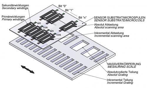
For the absolute measuring encoder, an additional coded pattern is used in parallel to the periodic grating pitch with code-sharing (Fig. 2). This encoding is detected by the scanning head inductively. The read binary word is unique for the full scale length and thereafter is a “look up table” to convert the data into an absolute linear or angular value. For high-resolution positioning, the evaluation of the incremental graduation, as described above, is merged with the absolute position.
Submicron resolution
Up to about 30 000 mm in length, or diameter up to 10 000 mm, with resolutions in the submicron range, are possible. The position data are transmitted via serial interfaces (EnDat 2.2, DRIVE-CLiQ, Fanuc, SSI, BISS, Mitsubishi).
*DRIVE-CLiQ is a registered trademark of Siemens AG.


